How to Make a Curved World Shader Graph (Subway Surfers)
Let's learn how to make a curved world shader graph like Subway Surfers. This is a simple version of this shader graph, compared to some of the ones I've seen. Simple isn't necessarily better, but it will help get you started with a better understanding of shaders, and you can customize them down the line if you so choose.
Watch: How to Make a Curved World Shader Graph
Don't want to read? No problem.
Breaking Down the Shader
Taking a look at Subway Surfers' gameplay, let's make 2 important observations:
- Number 1, they have this cool rolling globe-like effect similar to Animal Crossing's world.
- It's not only bending like a globe backward, but it's also bending to the side as well so that the player has a better view of what's coming up, literally, around the bend.
We now know that we need 2 things to happen to get this right.
The farther away the road is from the player, curve the world backward and to the side. In other words, the world needs to curve exponentially depending on the player's position. The key word here is exponential.
The Math Behind the Shader

We're going to be making this effect using shader graph, which is only available in URP or HDRP.
Create > shader graph > URP > and then Lit Shader Graph.
All Lit means is that we want our shader to be affected by light.
Since we want this effect to be more intense the farther away the plane and the objects are from the player, we need to know where the player is in the world first. The easiest way to do this, in this scenario, is to find the camera's position. The camera will have a script on it that will be following the player like all 3rd person games have, so this is essentially just a way to calculate where the player is.
We're going to add a position node and a camera node. The position node provides you with the position of the object that the shader is on. We can also pull the position of the camera with the camera node. And since we want to calculate the distance between the object and the camera, we're going to add in a subtract node to find that value.
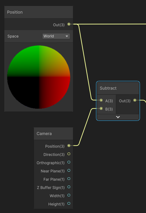
We are then going to subtract the camera position from the world position of the object using the subtract node.
But, since we only want this effect to happen when the player is moving to the front or to the back, not when moving side to side, we need to extract only the Z value from this equation. We only care if the player is changing their value along the Z axis. To do this, we're going to extract the Z value from this Vector 3 value, using a split node. It's a little confusing because the values say RGBA, but you can also use this when it comes to vectors, and in the case of vectors these values are really XYZ and W.
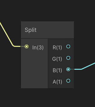
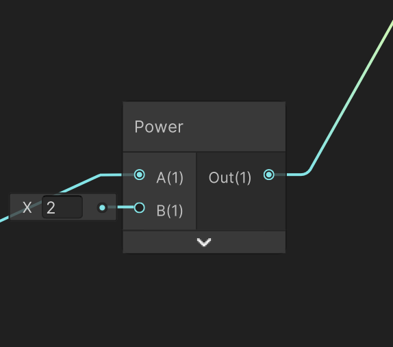
In this case, B is equal to Z, and from here, we want to alter the z value. This is where our exponential effect comes in. We're going to plug our Z value into a Power node, power as in X to the power of 2, if we remember our parabola formula from earlier.
But what if we want to be able to control the strength of the curvature, either from front to back, or from side to side. And what if we want the side-to-side curvature to be stronger than the front-to-back curvature?
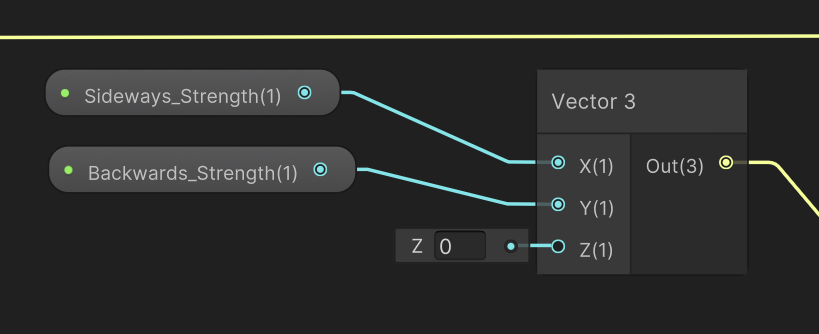
Well, in that case, we need to add a vector 3 node. Since I want to be able to control these values from the inspector, I'm going to create 2 float nodes and turn them into properties. One is going to be Sideways Strength, and the other is going to be Backwards Strength. And we'll plug Sideways strength into the X slot, and the Backwards strength into the Y slot. And we're going to leave the Z value at 0 here so that it is unchanged. X to the power of 0 is still 0, so there's no reason to use a Vector 2 instead of a Vector 3 and have to do weird math gymnastics.
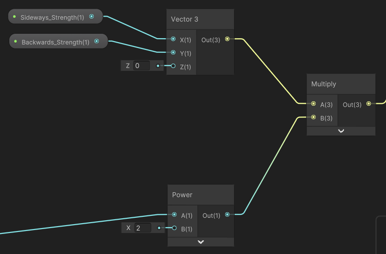
Now that I have that, I need to multiply my new values by the power node, so that we get that exponential effect. It's also a good idea when working with shader graph to constantly be thinking about what your final output is, and what you're looking for. What we're really doing with this, is changing the position of a mesh so we're ultimately looking for a Vector 3 value.
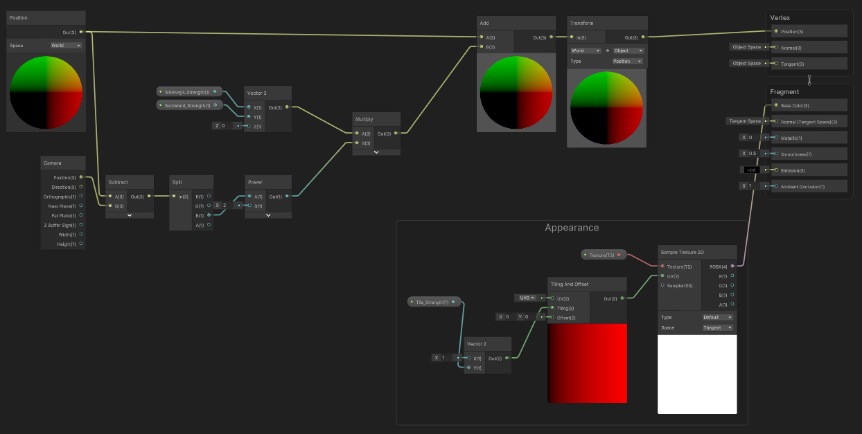
Now that we have our formula, our new values, we can create an add node, add in those values, and plug back in the position of the object. So that as the position of the camera and player changes, the shader is updating the position of the mesh.
The last thing to do before we plug this into the final output node is add a transform node. The original position node is using world space, which is what we want. We want to access the position information of the object in regards to the entire scene, not to itself, however, the final output node only accepts vector 3 values in object space, so we just have to convert it at the end.
Adding this Shader to Objects
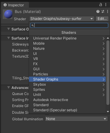
Now, let's switch back to the editor and apply this to an object. To apply a shader to an object, we first have to create a new material. To add a shader to this material, I need to find the shader dropdown. The default is the universal render pipeline, but if I click into the dropdown, I can see a section for Shader Graph shaders, which the shader we just created is under. With that done, I can drag and drop my new material onto my objects.
Now if we click on our object we can see the properties that we created and adjust from the editor. Since this effect is exponential, it doesn't take very high values to have a big effect, so I've been starting my numbers around .001.
Changing the Appearance of our Objects
What if we want to apply this to 3d objects, like a bus or walls, and what if we want to change the appearance of our materials?
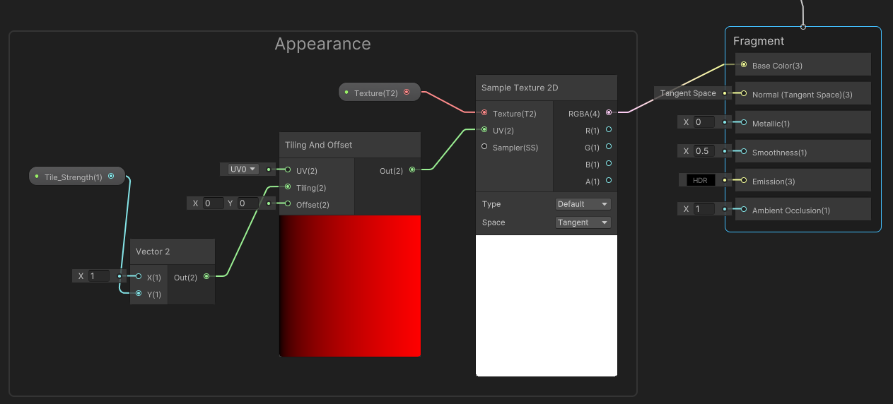
Inside shader graph, if we want to add a texture, we need to add a sample texture 2D node and plug it into the base color. You could plug a texture in here and call it a day, but I'm going to add a 2D texture asset node, turn this into a property and then plug it into the texture slot here so I can add textures from the inspector.
Now if we want to tile our texture, we need to add a tiling and offset node, and plug this into the UV slot on our sample texture 2d node. Now the tiling slot takes 2 values, an X and a Y, but if I change one and not the other, I'm going to get some weird stretching happening, so I ideally want these values to be the same so the scale is always the same.
Therefore I'm going to add a vector 2 node here, but control it with a single value plugging in a float value here, and then turning it into a property so that I can control it from the inspector. Also, make sure that value on the vector 2 is 1 instead of 0 or else you won't get any tiling. I'm only plugging the float into the Y slot because I only want to tile one way. If you want to tile both ways, you can plug the float value into the X and the Y slot.

What if my Objects Don't Look Right?
Now...if I want to create the walls and the buses, I might have a problem. Planes look great, but if I add a cube object here and scale it up you may notice that it's not curving exponentially. It is changing, but not in the way that we want it to. And that is because the default cube object in Unity only has 8 vertices. So Unity is accounting for those 8 vertices, but what about the entire section in-between those vertices? There's nothing there for Unity to change.
If you want a cube shape with more vertices, the easiest way I could think of was to create a cube in Blender, add a lot of loop cuts, and reimport to Unity.
Keep in mind that every object in the scene will need this shader attached or the objects will float/sink and look odd.
Thanks for reading!